Power Factor, Load and the Magnetising Current
Why an induction motor's power factor is poor at light load and improves as it takes on load
An induction motor draws two different things from the supply at the same time. One part does the work, turning the pump, driving the fan, lifting the load. The other part does no work at all. It sets up and holds the magnetic field the motor needs before it can produce any torque. Power factor is the relationship between those two parts, and the reason it changes with load comes down to a single fact. The working part grows with load, while the magnetising part stays roughly constant. That second part is the one most people skip over, so it is worth being clear about what it is and why it barely moves. Once that is on the table, the rest follows.
The field has to be there before anything turns
Before an induction motor can turn anything, it has to build a magnetic field, so it is worth a quick look at how the motor is put together.
An induction motor has two main parts, a stationary stator on the outside and a rotor that turns inside it. The stator carries three sets of windings, one for each phase, spaced around the core. When three-phase current flows through them, the windings produce a magnetic field that rotates around the inside of the stator at the supply frequency. That rotating field crosses the air gap and induces currents in the rotor bars, and those induced currents produce a field of their own. The two fields pull against each other and drag the rotor round. The rotor always turns a little slower than the field, and that small difference, called slip, is what allows the induction to happen in the first place. Figure 1.Inside a three-phase induction motor. The stator windings set up a rotating field that crosses the air gap and drives the rotor.
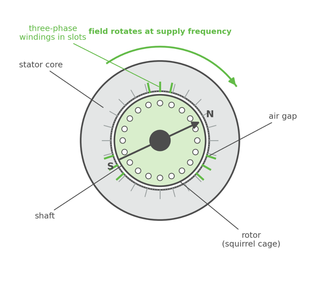
Figure 1.Inside a three-phase induction motor. The stator windings set up a rotating field that crosses the air gap and drives the rotor.
Building and holding that rotating field takes current, and we call it the magnetising current.
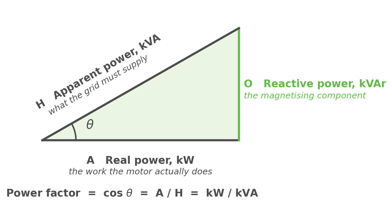
The magnetising current is reactive, which means it does no work. It flows out to set up the magnetic field, and as the field collapses and rebuilds fifty times a second it flows straight back again. Energy moves in and out of the magnetic field without being consumed. We measure that reactive flow in kVAr, and it is the O side of the power triangle.
The size of the magnetising current is set mostly by the supply voltage, the frequency and the iron itself, the number of turns, the air gap and the magnetic properties of the core. It is not set by how hard the motor is working. A motor at no load holds almost the same magnetic field as that same motor at full load, so it draws almost the same magnetising kVAr either way. That is the fixed part of the picture, and it is what makes power factor depend so strongly on load.
Three ways of measuring the same supply
A, the base, is the real power in kW. This is the actual work, turning the pump, driving the fan, lifting the load, plus the losses. It is the part of the current that lines up with the voltage.
O, the vertical, is the reactive power in kVAr. This is the magnetising component. It sits ninety degrees out of phase with the voltage, which is exactly why it does no work but still has to be supplied.
H, the hypotenuse, is the apparent power in kVA. This is what the grid actually has to deliver, the full current at the full voltage, regardless of how much of it ends up doing useful work.
Power factor is the ratio of the useful part to the total, cos θ, which is A divided by H, or kW divided by kVA. A power factor of 1 means everything the grid sends you is doing work. A power factor of 0.5 means half of what the grid sends you is just magnetising iron and moving back and forth.
What happens as the motor loads up
Now watch what happens to each side of the triangle as the motor takes on load.
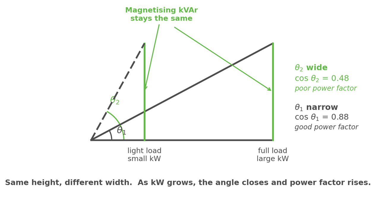
The vertical side, the magnetising kVAr, barely moves. It is roughly the same at light load as it is at full load, because the magnetic field is roughly the same. So, picture that vertical line as a fixed height.
The horizontal side, the real power in kW, is the part that grows with load. At light load the motor is doing very little work, so A is short. The triangle is tall and thin, the angle θ₂ is wide, and cos θ₂ is small. Poor power factor. At full load the motor is doing a lot of work, so A is long. With the same height and a much longer base, the triangle flattens out, the angle θ₁ closes up, and cos θ₁ is large. Good power factor.
So loading the motor does not reduce the reactive power. The reactive power is still there, roughly unchanged. What changes is that the real power has grown enough for that fixed reactive component to be a smaller share of the total. Same height, different width.
This is why an oversized or lightly loaded motor is a classic power factor problem. Fit a 30 kW motor to a duty that only needs 8 kW and the motor still draws close to its full magnetising kVAr while delivering 8 kW of real work, so the power factor on that circuit will always read poorly.
The shape of it
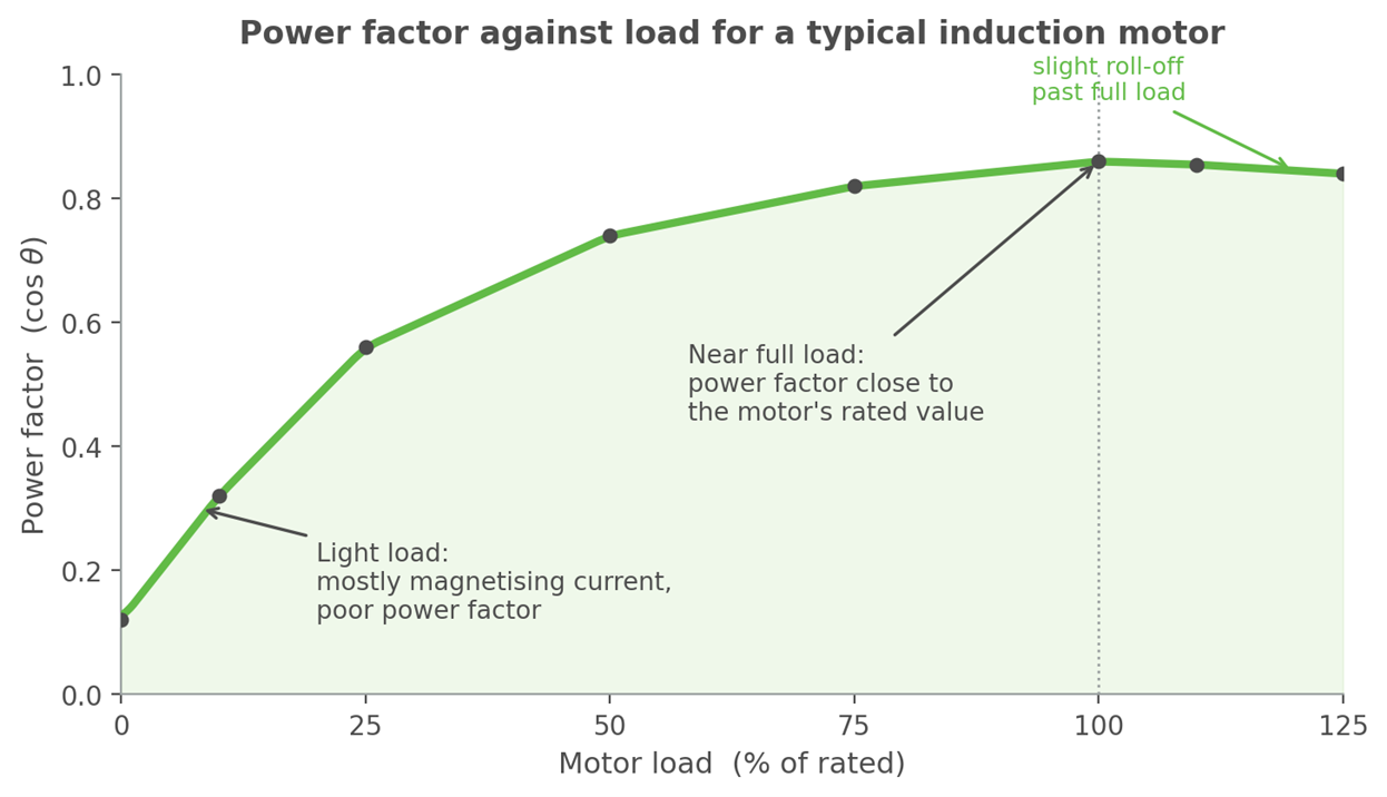
Plot power factor against load and you get a curve that climbs steeply at first and then levels off near the motor's rated value.
At no load, power factor can sit as low as 0.1 to 0.2. By half load it is usually up around 0.7. By full load it is up at the motor's nameplate figure, typically somewhere between 0.8 and 0.9 depending on the design. The steep part of that curve, down in the bottom left, is where a lot of real installations actually live, motors running part loaded because they were sized for a worst case, or for a duty that rarely turns up.
One complication.
The magnetising kVAr is not perfectly constant. It is the dominant reactive term at light load, but once real load current is flowing there is a second source of reactive power, the leakage reactance of the stator and rotor windings. That leakage reactive power grows with the square of the current, so it climbs as the motor takes on load.
Up to rated load the growth in real power wins easily and power factor keeps improving. Push the motor past its rating, though, and the leakage reactive power starts to grow faster than the real power, and power factor rolls off slightly again. That is the small downturn at the right hand end of the curve. For everyday purposes the headline still holds. Light load, poor power factor. Working load, good power factor.
What this can mean on site
A poor power factor on a motor circuit is not always a fault to be corrected with capacitors. Sometimes it is just a motor that is barely working, and the real fix is to match the motor to the duty rather than chase the symptom with correction gear. The only way to tell which one you are looking at is to measure it, under real load, and see where on that curve the motor actually sits.
It is worth being clear about what a poor power factor at light load actually costs you. It is not a safety problem, and it will not damage the motor. The cost shows up on the bill though. Reactive energy is commonly charged on a kVAr/h basis, or through a power factor penalty, and a lightly loaded motor sits there drawing its magnetising kVAr whether it is doing useful work or not. So, a row of part loaded motors can quietly add to what you pay each month while producing very little in return. You pay the same charge regardless of load.
References and further reading
If this topic is interesting enough for you to dive into further information, we would recommend looking up the following.
- Chapman, S. J. (2012). Electric Machinery Fundamentals (5th ed.). McGraw-Hill. The induction motor chapter covers the equivalent circuit, the magnetising reactance and how power factor varies with load.
- Umans, S. D. (2014). Fitzgerald and Kingsley's Electric Machinery (7th ed.). McGraw-Hill. Magnetising current, the induction machine equivalent circuit and the treatment of reactive power.
- IEEE Std 1459-2010 (revised 2025), Standard Definitions for the Measurement of Electric Power Quantities Under Sinusoidal, Nonsinusoidal, Balanced, or Unbalanced Conditions. Formal definitions of active, reactive and apparent power, and of power factor. standards.ieee.org/ieee/1459
- Specification of Electric Motors (technical guide). Manufacturer reference noting that a motor draws reactive power for magnetisation that does no work, and that power factor changes with motor load. static.weg.net (PDF)
- Energy Efficiency and Conservation Authority (EECA). Three-phase electric motors: Minimum Energy Performance Standards. New Zealand E3 Programme. Motor efficiency is set and tested at 75 and 100 percent of rated load. govt.nz
About the author
kVAr Solutions provides power quality testing and solutions for commercial and industrial sites across New Zealand. We measure what is actually happening on a system, using proper instrumentation logged under real operating conditions rather than a quick spot check, then work out what is driving the problem, what it is costing, and what to do about it. Where correction is the answer, we design and manufacture power factor correction (PFC) units and active harmonic filters (AHFs) built to suit the site. The work runs from one-off investigations and meter hire through to engineered and manufactured solutions, with reports and recommendations written so the people paying for them can follow the reasoning.
Andy Whitten writes articles focussing on power factor, harmonics and the other power quality problems that turn up on real commercial and industrial sites. The goal is to write articles to be plain enough that an electrician or engineer can hand one to their clients and have the idea land, while still holding the detail a technical reader needs. The aim is simple, to make the thing make sense to whoever is reading it. You can find all the articles at www.kvar.co.nz/resources/white-papers
Feedback and suggestions are always appreciated, so if something could be clearer or you want a topic covered, get in touch.